I've completed reassembly of the CopyPro CP2000, with a new mainboard, consisting of a chunk of MDF, with an Arduino, Motor Board, Stripboard & breadboard, and Kryoflux attached to it..
All in the same space of the original..
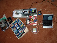
Here's a pic of it all before I made all the cables internal..
And here's a quick video of it working, reading a few disks..
 |
| New Controller Board fitted |
This gave me a gap that was an ideal size to stuff a breadboard into, and with all the power & sensors now surfaced as female headers, ideal for hooking up with yet more jumper wires.

Plonked in some resistors to limit the current to the IR diodes, and fed the photo transistor outputs across to the Arduino pins. Quick test showed them reading 0 when unobstructed, and 1 when obstructed.


 Tracing out a PCB isn't that hard.. just take some carefully aimed photos using a bright lamp, then import to Photoshop, align the layers, and off you go..
 That left creating the code to control the device..
Turns out one sensor goes to 0 when the disk insertion carriage is at its furthest extents.. (this is kind of important, as the motor must be stopped then, to prevent it straining against the edge of the allowed motion).. slight issue that you can't really tell _which_ extent.. has it just put a disk in? or is it waiting to do that?
I ended up moving the carriage forward/back a bit, monitoring the sensor, to figure out if it went 1/0 then it was waiting to put a disk in.. if it stayed 0/0, then it was fully forward after putting a disk in. Once the Arduino knew where it was, it could use that until the next power up.
The insert/eject code was otherwise quite simple, to insert; move carriage forward until either the carriage is fully forward, or until the disk mouth sensor does a 1/0 transition.. to eject; bring the carriage back until you notice the disk mouth sensor go 0/1, or until the carriage is fully backward. (Originally, I tried just bringing the carriage backward, but that can result in the eject button being pressed too hard, and the drive tilted in a way that means disks don't exit cleanly).
For both insert/eject, have to be very careful to track that the disk went in ok, and exited the unit ok.. the force the unit can generate to insert a disk is quite fearsome, and it's best it doesn't try to put two disks in the drive at the same time..
I wrapped all that in a simple serial protocol, (serial over usb), and hooked that up to some Java using the rxtx library.
Both the arduino & the java host s/w run mini state machines, tracking what they are attempting to do, and testing if it looks like that occured ok.. The host relies on the status coming back from the arduino to know if things are still ok, and coordinates performing that initial carriage position seek, inserting disks, invoking the Kryoflux disk imaging commandline tool, ejecting the disk, grabbing an image of the last ejected disk via a webcam, then inserting the next & repeating..
I just need to build the 'replacement' input & output chutes, as this unit lost its original ones at some distant point in the past.
At the mo, I've seen it work through 10 disks, and create Stream & ADFs for each of them.. although I do have to stop wondering why I hear the catflap open/close each time it does an insert/eject.. it's most confusing, as I don't have a catflap anymore..
No comments :
Post a Comment